DPDK (Data Plane Development Kit) is a set of libraries for implementing user space drivers for NICs (Network Interface Controllers). It provides a set of abstractions which allows a sophisticated packet processing pipeline to be programmed. But how does DPDK work? How is it able to access the hardware directly? How does it communicate with the hardware? Why does it require a UIO module (Userspace input-output)? What are hugepages and why are they so crucial?
In this blog post I will try to explain, with a reasonable amount of detail, how a standard kernel space NIC driver works, how a user space program can access hardware and what can be gained from having it do so.
Linux networking software stack
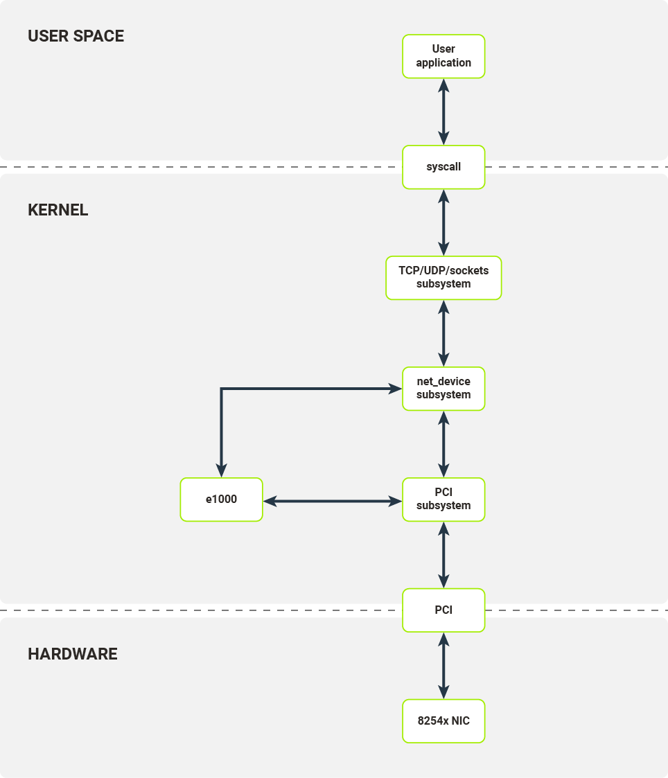
Diagram 1. Software layers of a networking stack on Linux
Before diving into the low-level details, let’s examine how a standard networking software stack on Linux works.
Any user application which seeks to establish a TCP connection or send a UDP packet has to use the sockets API, exposed by libc. In the case of TCP, internally several syscalls are used:
- socket() - allocates a socket and a file descriptor;
- bind() - binds a socket to an IP address and/or protocol port pair (application specifies both or lets the kernel choose the port);
- listen() - sets up connection queue (only for TCP);
- accept4() - accepts an established connection;
- recvfrom() - receives bytes waiting on the socket (if there are any, in the case of empty read buffer block);
- sendmsg() - sends a buffer over the socket.
Call to each of these kernel side functions invokes a context switch, which eats up precious compute resources. During a context switch, the following steps are executed:
- Userspace software calls kernel side function;
- The CPU state (user application) is stored in memory;
- CPU privilege mode is changed from underprivileged to privileged (from ring 3 to ring 0); privileged mode allows for more control over the host system, e.g. access IO ports, configure page tables;
- The CPU state (kernel) is recovered from memory;
- Kernel code (for a given code) is invoked.
Let’s assume that our application wants to send some data. Before the application’s data goes onto the wire it is passed through several layers of kernel software.
Kernel socket API prepares an sk_buff structure, which is a container for packet data and metadata. Depending on the underlying protocols (network layer - IPv4/IPv6 and transport layer - TCP/UDP) the socket API pushes the sk_buff structure to underlying protocol implementations of the send operation. These implementations add lower layer data such as port numbers and/or network addresses.
After passing through the higher level protocol layers, prepared sk_buffs are then passed to the netdev subsystem. The network device along with the corresponding netdev structure responsible for sending this packet are chosen based on IP routing rules in Linux kernel. The netdev structure’s TX callbacks are then called.
The netdev interface enables any module to register itself as a layer 2 network device in Linux kernel. Each module has to provide the ability to configure the device’s offload, inspect statistics and transmit packets. Packet reception is handled through a separate interface. When ready for transmission by the NIC, the prepared sk_buff is passed to netdev’s TX callback, which is a function of the kernel module.
The last step moves us into concrete device driver territory. In our example, that device is the e1000 driver for the family of 8254x NICs.
After receiving a TX request from the upper driver layers, the e1000 driver configures the packet buffer, signals to the device that there is a new packet to be sent and notifies the upper layer once the packet has been transmitted (note that that is not the equivalent of successful reception on the other endpoint).
Today, the most commonly used interface for communication between kernel drivers and network devices is a PCI bus, e.g. PCI Express.
To communicate with a PCI device, the e1000 kernel module has to register itself as a PCI driver in Linux’s PCI subsystem. The PCI subsystem handles all the plumbing required to correctly configure PCI devices: bus enumeration, memory mapping and interrupt configuration. The e1000 kernel module registers itself as a driver for a specific device (identified by vendor ID and device ID). When an appropriate device is connected to the system, the e1000 module is called to initialize the device - that is, to configure the device itself and register the new netdev.
The next two sections explain how the NIC and kernel module communicate over the PCI bus.

Interfaces between the NIC and kernel
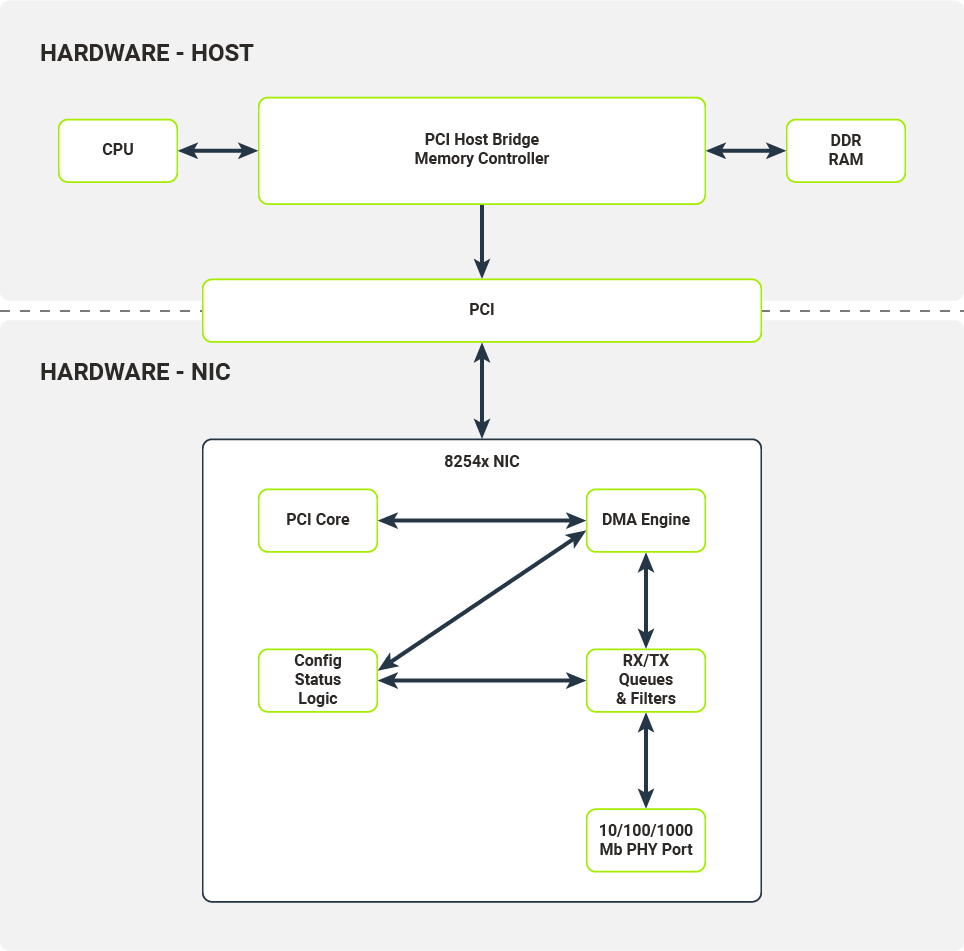
Diagram 2. Relationships between the hardware components on the NIC and the host system
On Diagram 2, the hardware architecture of a typical computer system with a network device attached on a PCI bus is presented. We will use the 8254x NICs family, more specifically their single port variants, as in the example.
The most important components of the NIC are:
- 10/100/1000 Mb PHY Port
- RX/TX Queues & Filters
- Config/Status/Logic Registers
- PCI Core
- DMA Engine
10/100/1000 Mb PHY Port
The hardware component responsible for encoding/decoding packets on the wire.
RX/TX Queues & Filters
Typically implemented as hardware FIFOs (First-In First-Out queues), RX/TX Queues directly connect to PHY ports (Physical Ethernet Ports). Frames decoded by PHY port are pushed onto the RX queue (a single queue on 8254x NICs) and later consumed by the DMA Engine (Direct Memory Access Engine). Frames ready to be transmitted are pushed onto TX queues and later consumed by the PHY Port. Before being pushed onto RX queues, the received frames are processed by a set of configurable filters (e.g. Destination MAC filter, VLAN filter, Multicast filter). Once a frame passes the filter test, it is pushed onto the RX queue with appropriate metadata attached (e.g. VLAN tag).
Config/Status/Logic
The Config/Status/Logic module consists of the hardware components that configure and control the NIC’s behavior. The driver can interact with this module through a set of configuration registers mapped to physical RAM. Writes and reads from certain locations in physical RAM will be propagated to the NIC. The Config/Status/Logic module controls the behaviour of RX/TX queues and filters, and collects traffic statistics from them. It also instructs the DMA Engine to perform DMA transactions (e.g. transfer data packets from the RX queue to the host’s memory).
PCI Core
The PCI Core module provides an interface between the NIC and host over the PCI bus. It handles all the necessary bus communications, memory mappings and emits interrupts received by the host’s CPU.
DMA Engine
The DMA Engine module handles and orchestrates DMA transactions from the NIC’s memory (packet queues) to the host’s memory over the PCI bus.
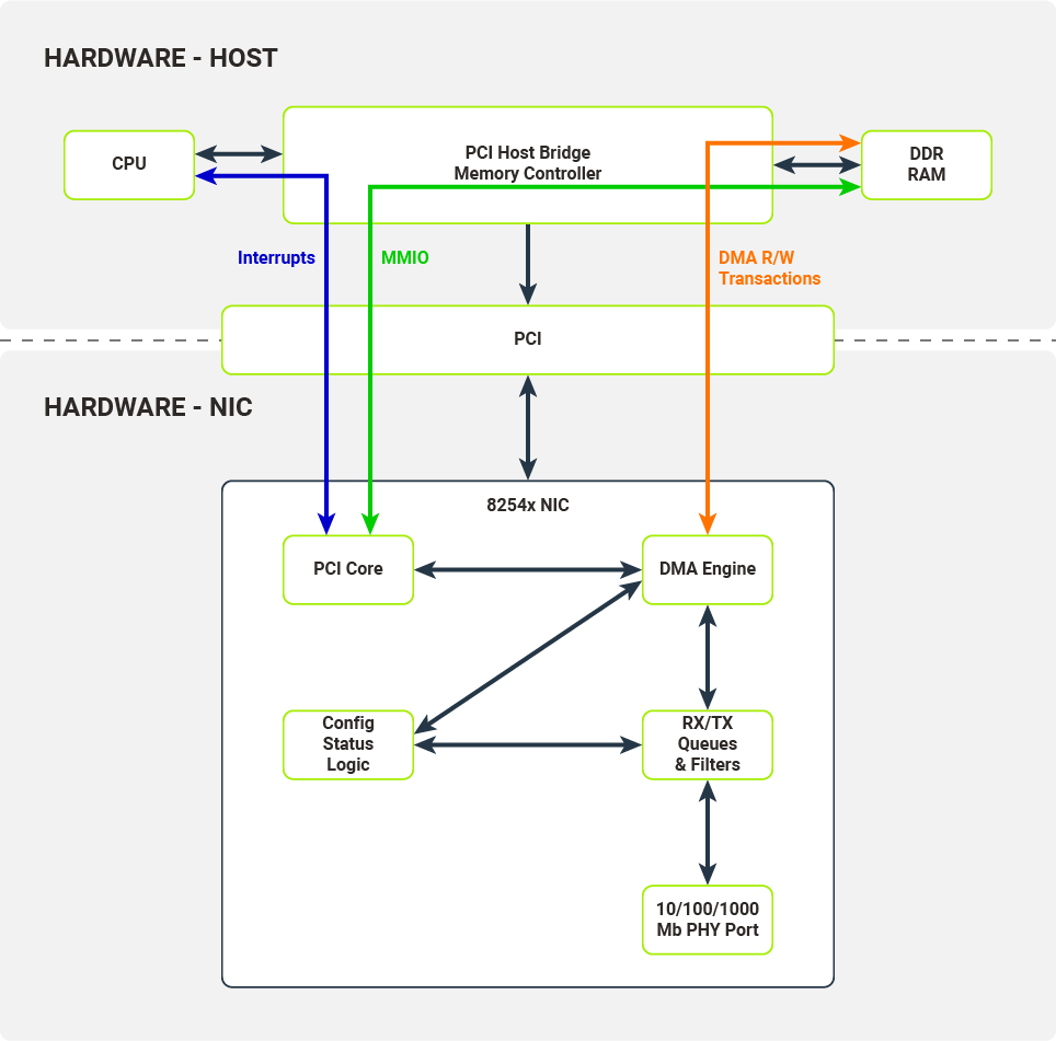
Diagram 3. Communication interfaces exposed by the NIC and consumed by the host's hardware
The Host and the NIC communicate across several interfaces over the PCI bus. These interfaces are utilized by kernel drivers to configure the NIC and receive/transmit data from/to packet queues.
MMIO (Memory-Mapped Input-Output)
Configuration registers are memory-mapped to the host’s memory.
Interrupts
NIC fires interrupts on specific events, e.g. link status change or packet reception.
DMA R/W Transactions (DMA Read/Write Transactions)
Packet data is copied to the host's memory from the NIC packet queue (when received) or copied to the NIC packet queue from the host’s memory (when transmitted). These data transfers are carried out without the host’s CPU intervening and is controlled by the DMA Engine.
NIC to kernel data flow
To better understand the data flow between the NIC and the kernel, we now turn to the RX data flow. We will go step by step and discuss the data structures required by the NIC and kernel driver in order to receive packets.
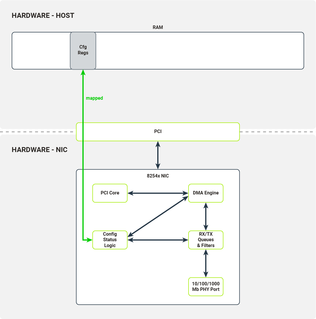
Diagram 4. Configuration registers are mapped into the host's memory
After the NIC has been registered by the kernel PCI subsystem the driver enables MMIO for this device by mapping IO memory regions to the kernel address space. The driver will use this memory region to access the NIC’s configuration registers and control its function. The driver can, for example:
- check link status
- mask/unmask interrupts
- override Ethernet auto-negotiation options
- read/write Flash/EEPROM memory on NIC
When a driver wants to configure packet reception, it accesses the following set of configuration registers:
- Receive Control Register - enables/disables packet reception, configures RX filters, sets the RX buffer size;
- Receive Descriptor Base Address - the base address of the receive descriptor buffer;
- Receive Descriptor Length - the maximum size of the receive descriptor buffer;
- Receive Descriptor Head/Tail - offsets from the beginning of the receive descriptor buffer they point to head/tail of the receive descriptor queue;
- Interrupt Mask Set/Read - unmask/mask (enable/disable) packet reception interrupts.
Most of the configuration registers are used to set up a receive descriptor buffer.
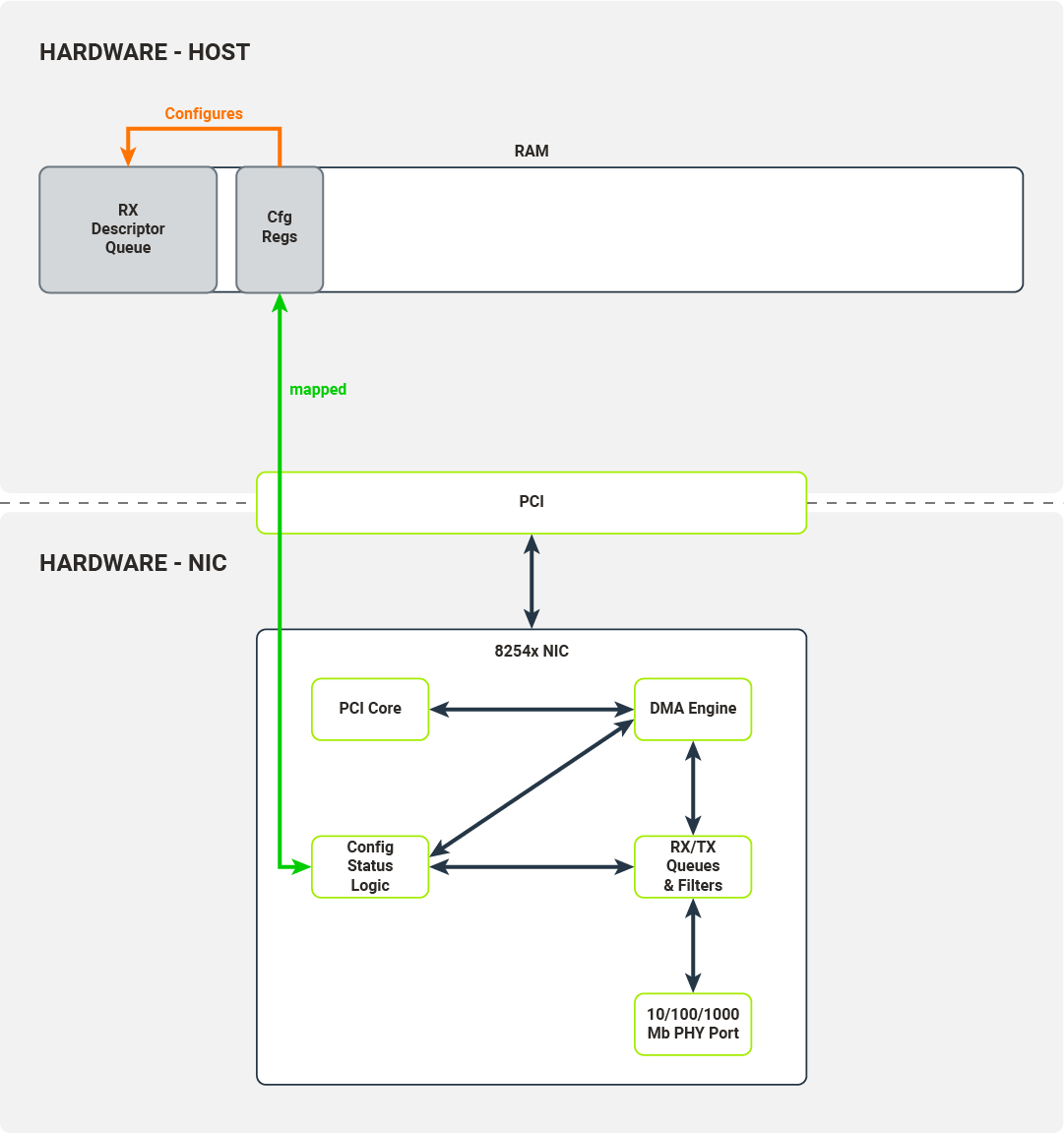
Diagram 5. Configuration registers describe the location of the RX descriptor buffer queue
The received descriptor buffer is a contiguous array of packet descriptors. Each descriptor describes the physical memory locations where the packet data will be transferred by the NIC and contains status fields determining which filters the packets have passed. The kernel driver is responsible for allocating the packet buffers which can be written to by the NIC’s DMA engine. After successful allocation, the driver puts these buffers’ physical addresses into packet descriptors.
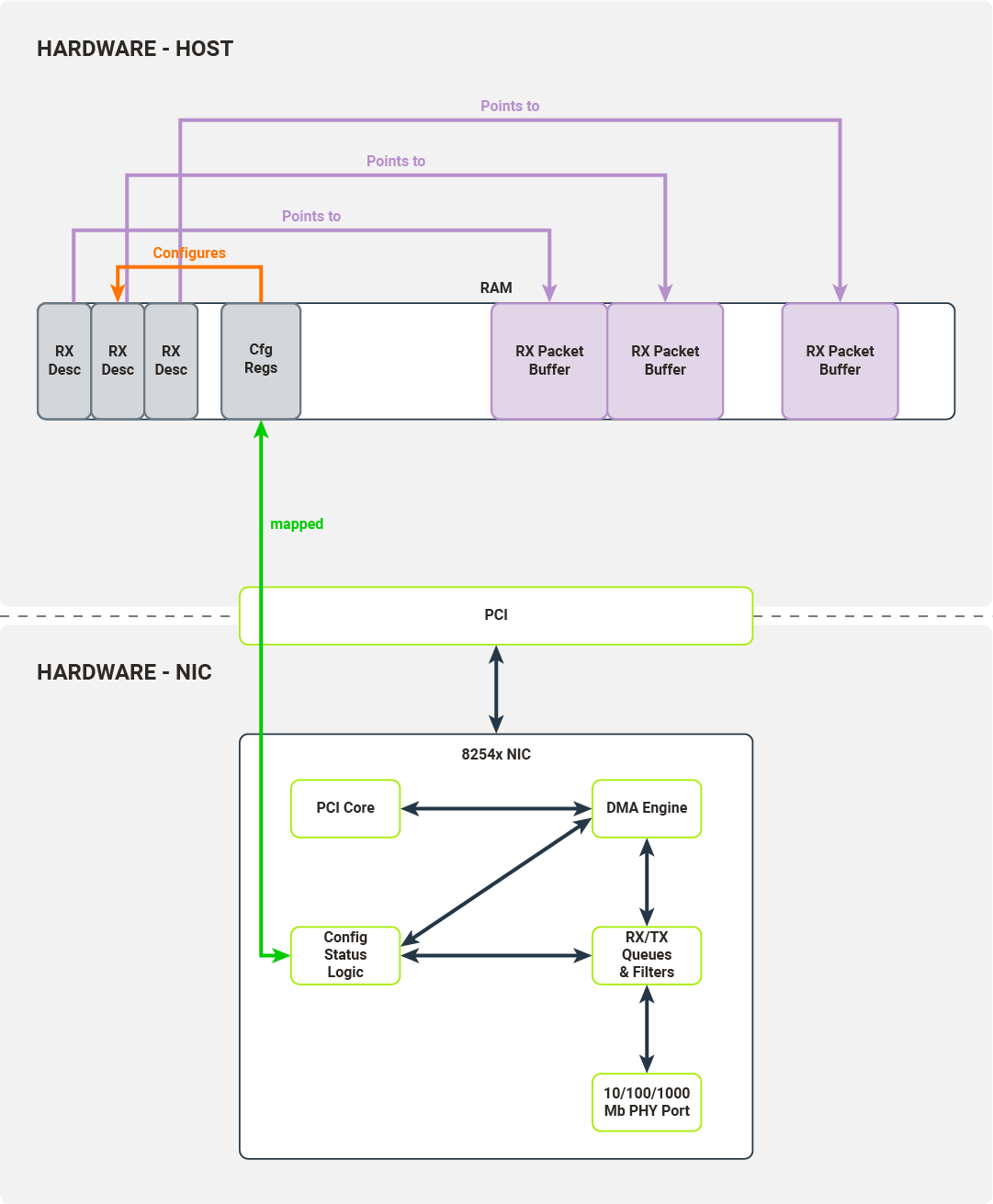
Diagram 6. Each RX descriptor has a memory pointer describing the location of the corresponding packet buffer
The driver writes the packet descriptor buffer’s base address into the configuration register, initializes the receive descriptor queue (by initializing head/tail registers) and enables packet reception.
Once the PHY Port has received a packet, it pushes it onto the NIC’s RX queue and traverses a configured filter. Packets ready to be transferred to hosts are transferred by the DMA engine to the hosts’ memory. The destination memory location is taken from the tail of the descriptor queue.
The DMA Engine updates the status fields in the tail of the descriptor queue and, after the operation is finished, the NIC increments the tail. Finally, the PCI Core generates an interrupt to the host, signaling that another packet is ready to be retrieved by the driver.
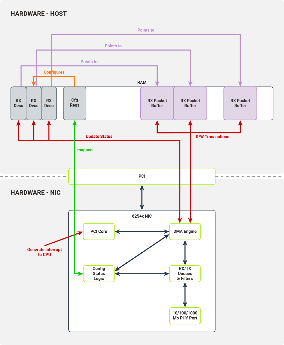
Diagram 7. Interfaces utilized to transfer a packet to the host's memory and signal to the host that the packet has been received
A symmetrical process is carried out for the packet transmission path. The kernel driver puts packet data in the packet buffer indicated by the memory location field in the descriptor under the tail pointer. The kernel driver marks the packet as ready to transmit and increments the tail pointer.
When the head and tail pointer in the descriptor queue diverge, the NIC inspects a packet descriptor under the head pointer and initiates a DMA transaction to transfer the packet data from the host memory to the TX packet queue. When the transaction is complete, the NIC increments the head pointer.
User space drivers
We have covered how kernel space drivers communicate with hardware. DPDK, however, is a user space program, and user space cannot directly connect with hardware. This presents us with a few problems:
- How to access configuration registers;
- How to retrieve physical memory addresses of the memory allocated;
- How to prevent process memory from swapping in/out or moving during runtime;
- How to receive interrupts.
In this section we will discuss the mechanisms the Linux kernel provides to overcome these obstacles.
Why user space in the first place?
There are three primary reasons to move the drivers from the kernel to user space:
- Reduce the number of context switches required to process packet data - each syscall causes a context switch, which takes up time and resources.
- Reduce the amount of software on the stack - Linux kernel provides abstractions-- general purpose ones, in some sense--that can be used by any process; having a networking stack implemented only for specific use cases allows us to remove unnecessary abstractions, thus simplifying the solution and possibly improving performance.
- User space drivers are easier to develop than kernel drivers - if you want to develop a kernel driver for a very specific device, it might be hard to support. In the case of Linux, it would be beneficial to have it merged into a mainline kernel, which takes considerable time and effort. Moreover, you are bound by Linux’s release schedule. Finally, bugs in your driver may cause the kernel to crash.
UIO
Recall, for a moment, the Linux networking stack (Diagram 1). Interfaces used to communicate directly with the hardware are exposed by the kernel’s PCI subsystem and its memory management subsystem (mapping IO memory regions). In order for our user space driver to have direct access to the device, these interfaces must somehow be exposed. Linux can expose them by utilizing the UIO subsystem.
UIO (User space Input/Output) is a separate kernel module responsible for setting up user space abstractions, usable by user processes, to communicate with hardware. This module sets up internal kernel interfaces for device passthrough to user space. To use UIO for a PCI device, you’ll need to bind your NIC to uio_pci_generic driver (this process requires unbinding the device’s dedicated driver, e.g. the e1000, and manually binding the uio_pci_generic driver). This driver is a PCI driver that works with the UIO module to expose the device’s PCI interfaces to the userspace. The interfaces exposed by the UIO are presented in Diagram 8.
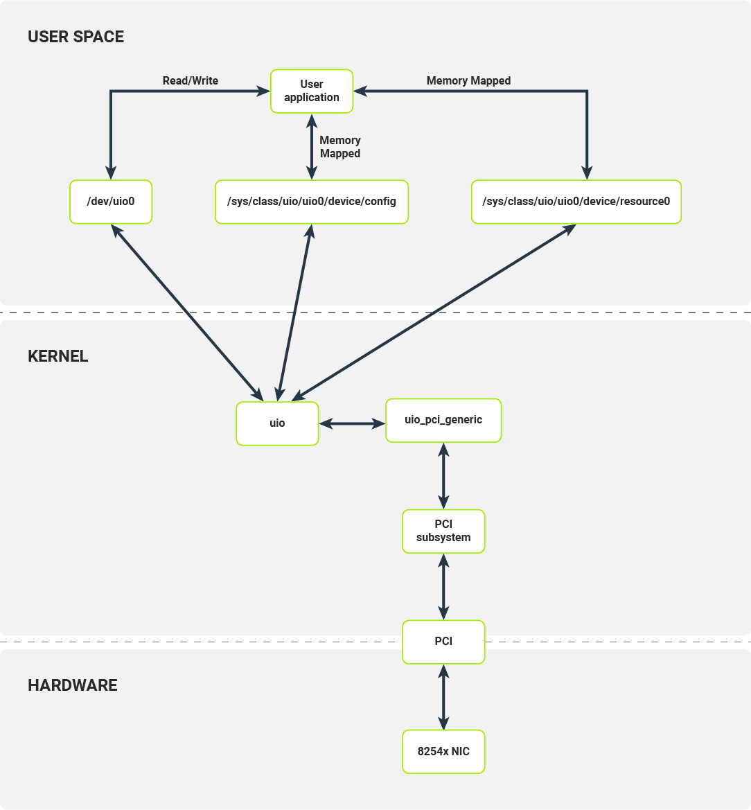
Diagram 8. Software layers of a networking stack on Linux when using UIO
For each bound device, the UIO module exposes a set of files with which user space applications can interact. In the case of the 8254x NIC, it exposes:
- /dev/uio0 - reads from this file allow the user space program to receive interrupts; read blocks until interrupt has been received; read() calls return the number of interrupts;
- /sys/class/uio/uio0/device/config - user space can read or mmap this file; it is directly mapped to PCI device configuration space where e.g. the device and vendor ID are stored;
- /sys/class/uio/uio0/device/resource0 - user space can mmap this file; it allows a user space program to access BAR0, first IO memory region of the PCI device, thus a user space program can read from/write to PCI device configuration registers.
In some sense UIO module only provides a set of memory translations allowing the user space process to configure the device and receive notifications on device events.
To properly implement a packet processing pipeline, we have to define an RX/TX descriptors buffer. Each descriptor buffer has a pointer (memory address), which points to preallocated packet buffers. The NIC only accepts the physical addresses as valid memory locations to run DMA transactions on, but processes have their own virtual address space. It is possible to find a physical address corresponding to each virtual address (using /proc/self/pagemap interface [pagemap documentation]), but this correspondence cannot be used consistently. There are a few reasons for this:
-
The process can be swapped out/in and change its location:
- Sidenote: This can be averted - mlock().
-
The process can be moved to another NUMA node and the kernel might move its memory:
- The Linux kernel does not guarantee that physical pages will stay in the same place during the process runtime.
This is where the hugepage mechanism becomes important.
Hugepages
On x86 architecture (both the 32- and 64-bit variants), standard physical pages are 4KB in size. Hugepages were introduced into the architecture to solve two problems:
- First, to reduce the number of page table entries required to represent contiguous chunks of memory bigger than 4KB. This reduces TLB usage, thus reducing TLB thrashing; (The TLB - Translation Lookaside Buffer - is in-CPU cache for page table entries);
- Second, to reduce the overall size of the page table.
On x86 architecture, depending on the hardware support, hugepages can be 2MB or 1GB in size. The Linux kernel memory management subsystem allows the administrator to reserve a hugepage pool that is usable by user space processes. By default, when the kernel is configured to preallocate the hugepages, the user space process can create a file in the /dev/hugepages directory. This directory is backed by a pseudo-filesystem, hugetlbfs. Each file created in this directory will be backed by hugepages from the preallocated pool. The user space process can create files of the size called for and then map them into their address space. The user space process can then extract the physical address of this memory region from /proc/self/pagemap and use it for packet buffers in the descriptor queue.
It is safe to use hugepages as memory backing the descriptor queue and packet buffers, because Linux kernel guarantees that the physical location will not change during runtime.
Diagram 9 illustrates an RX packet queue with changes showing which interfaces are consumed by the user space process.
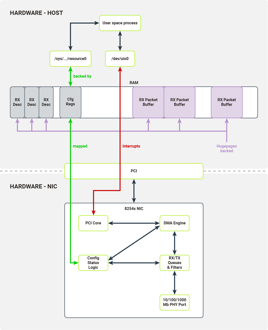
Diagram 9. Interfaces utilized by the user space driver to transfer a packet to the host's memory and signal to the host that packet has been received
Summary
In this article we have discussed:
- The standard packet processing pipeline in kernel drivers;
- Why user space processes cannot directly access hardware;
- Interfaces exposed by Linux kernel to user space which allow users to create user space drivers.
Since the subject is very vast, there are other important topics to be covered:
- How DPDK uses the interfaces we have presented;
- The workflow of a typical DPDK application;
- How the interfaces and application architecture we’ve presented allow DPDK to improve packet processing performance.


