The programming language P4 is gaining in popularity in the network industry and is considered the next step in the SDN evolution. In this blog post, I will take a closer look at P4 and try to show why it is so important.
What is the change?
Network devices like switches or routers are most commonly designed ”bottom-up.” The switch vendors that offer products to their clients usually rely on external chips from 3rd party silicon vendors. The chip is the heart of the system and in practice determines how device OS is realized and what functionality it can offer. Since the chip is a fixed-function unit and its internal packet processing pipeline cannot be easily reconfigured at runtime, adding a new feature set is a complex process that may take months. This is because a chip redesign is usually required.
P4 represents a completely different approach, similar to how the Central Processing Unit (CPU), Graphics Processing Unit (GPU) or Digital Signal Processor (DSP) work. These processing units execute code written in a specific programming language (e.g C++ for CPU, OpenCL for GPU or Matlab for DSP). The code is first compiled and then loaded into the processor. P4 is based on the same principle, but for network devices. This is a “top-down” approach. In contrast to the “bottom-up” paradigm, here the programmer defines the network feature set. It is defined in the P4 program. The code is then compiled and the configuration is injected into the network device. Of course, to enable this, you need to use a special type of chip. It can still have a number of fixed-function blocks inside, but it must also contain programmable blocks (see Figure 1).
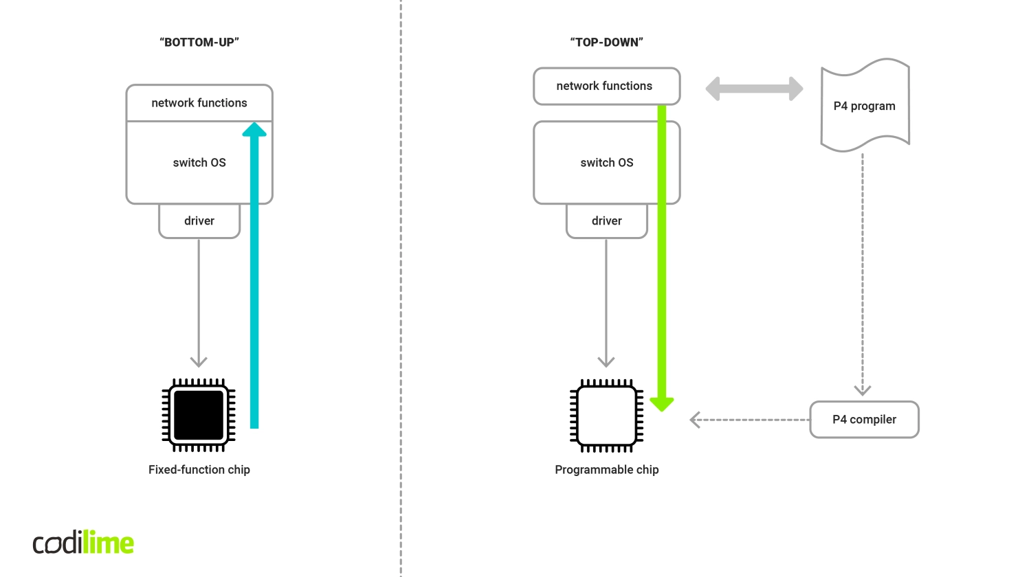
Fig 1. Bottom-up vs. top-down approach
The P4 programming language
P4 was first described in a paper entitled “Programming Protocol-Independent Packet Processors.” P4 allows a programmer to fully arbitrarily define how packets traversing programmable dataplane blocks will be processed. The commonly used term in P4 is a target, which represents a variety of devices—switch, router, Network Interface Card (NIC) inserted into the server, a software switch—which in general can be programmed using P4. The great advantage of P4 is that it allows for processing not only standard well-known protocol headers (e.g. Ethernet, IP, TCP, etc.) like traditional switches or routers normally do, but also fully custom ones, as presented in the example P4 code below:
// Ethernet header definition
header ethernet_t {
    bit<48>     dst_addr;
    bit<48>     src_addr;
    bit<16>     ethertype;
}
// IPv4 header definition
header ipv4_t {
    bit<4>       ver;
    bit<4>       ihl;
    bit<8>       diffserv;
    bit<16>      totlen;
    bit<16>      identification;
    bit<3>       flags;
    bit<13>      frag_offset;
    bit<8>       ttl;
    bit<8>       proto;
    bit<16>      hdrCSM;
    bit<32>      src_addr;
    bit<32>      dst_addr;
}

// custom protocol header definition
header myCustomProtocol_t {
    bit<16>      proto_id;
    bit<8>       vrtual_connection_id
    bit<8>       flags
    bit<16>      src_node_id;
    bit<16>      dst_node_id;
}

// a struct combining all headers
struct headers {
    ethernet_t     ethernet;
    myCustomProtocol_t myCustomProtocol;
    ipv4_t             ipv4;
}
All header types (both well-known and custom), as well as the way they are parsed, must be explicitly defined in the P4 program. It is also the programmer’s responsibility to design a so-called match-action pipeline within the given dataplane block. It can be composed of one or multiple tables where matching against parsed header fields takes place (see Figure 2).
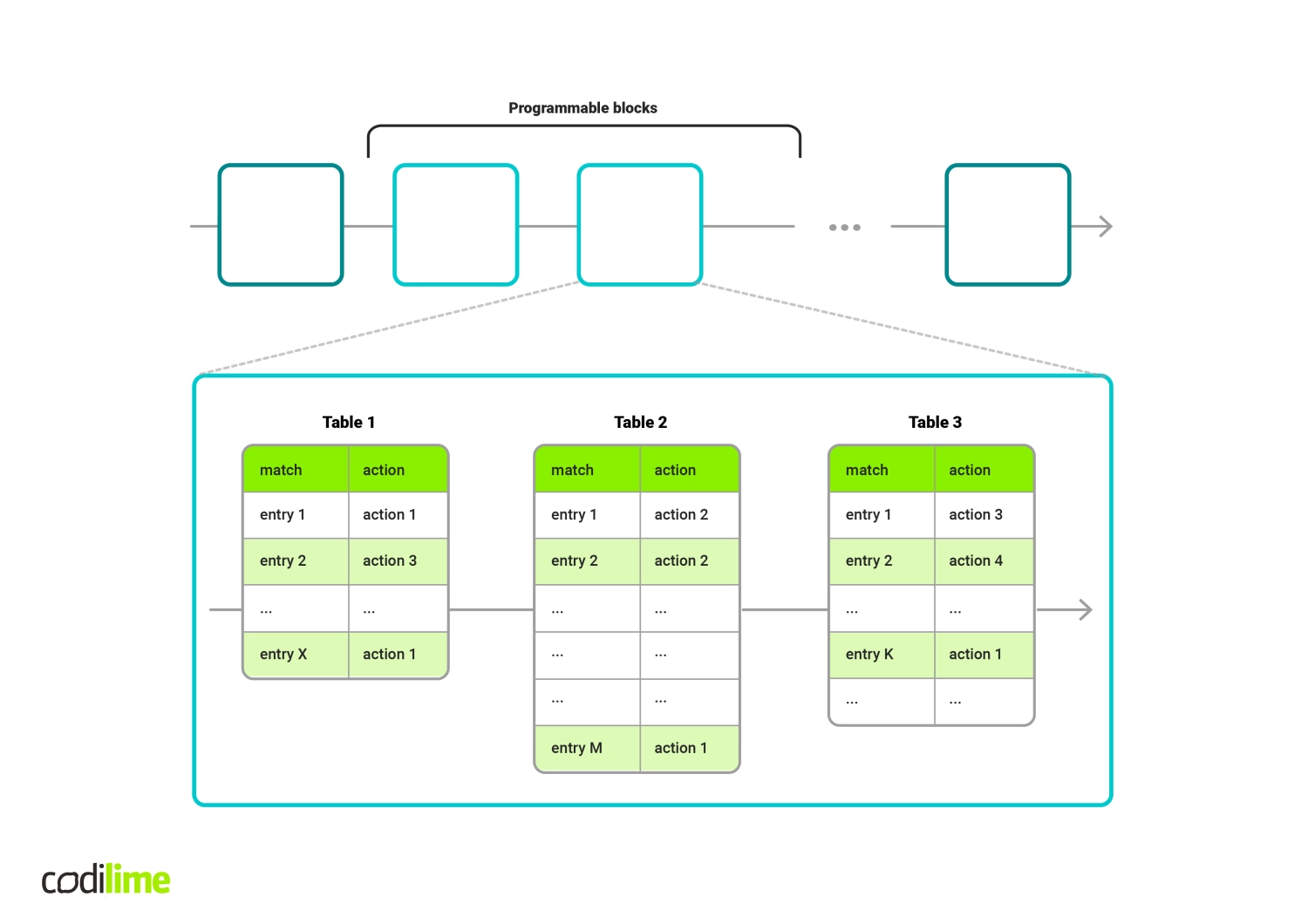
Fig 2. Example match-action pipeline within a given programmable block
For instance, the key section of the my_table table in the example below includes two match fields: hdr.ipv4.dstAddr and hdr.tcp.dstPort, corresponding to destination IP address and destination TCP port, respectively. For each table, one or more actions can be assigned to be executed at runtime (see action examples). Actions define what to do with the packet: modify the values of selected header fields, drop the packet, forward the packet to the chosen physical port, etc. Moreover, not only can packet header fields be processed in the tables, but so can standard or user-defined metadata assigned to packets. All the aspects related to tables and their internal structure (like number of tables, match fields and actions for each table, action’s behaviour, etc.) are left to the P4 programmer. This makes P4 a powerful solution.
action drop() {
        mark_to_drop();
}

action my_action_1(some_type_t arg1, bit<16> arg2) {

    //my_action_1 behaviour implementation here
    //(...)
}

action my_action_2(bit<8> arg1) {

    //my_action_2 behaviour implementation here
    //(...)
}

table my_table {
    key = {
        ph_hdr.ipv4.dst_addr: lpm;
        ph_hdr.tcp.dst_port: exact;
    }
    actions = {
        my_action_1;
        my_action_2;
        drop;
        NoAction;
    }
    size = 1024;
    default_action = drop();
}
The first P4 language release was called P414. The current language specification goes byP416. There are several differences between the two and it is worth noting that P416 introduces some backwards-incompatible changes to P414 in terms of both syntax and semantics. The key motivation for transformation from P414 to P416 was to reduce the complexity of the language (from more than 70 keywords to less than 40) and provide a stable core of the language in order to ensure that current P416 programs will be syntactically correct also in future, when examined against subsequent versions of the language. At the same time, a large number of native P414 language features have been moved into libraries of fundamental constructs needed for writing effective P4 programs. This includes target-specific implementations of some functions (e.g. counters, meters, checksum calculation, etc.), called externs.

P4 architecture model
P416 language specification introduces the architecture model. The P4 architecture model (in short: P4 architecture) as such identifies the function blocks that are present for a given dataplane target and also specifies the interfaces between them. In general, both fixed-function blocks and programmable blocks can exist for a given target. The behaviour of the fixed-function blocks is determined by the target manufacturer, leaving it out of P4 programmer’s control. Programmable blocks in turn are left to be programmed using P4. It is worth noting that P4 programs are not expected to be portable across different architecture models. However, programs created for the same architecture should be portable across all targets that conform to the considered model.
The detailed specification of the architecture must be provided by the target manufacturer. For that purpose the manufacturer provides a library P4 file (<some_architecture_model>.p4) containing all necessary declarations of functional blocks existing in the target pipeline, their types as well as other data types, constants, externs, etc. Only declarations of programmable blocks are included in the architecture definition model since, on principle, no single fixed-function block (if they are present in the target processing pipeline) can be manipulated by any P4 program. The programmable block has to be marked as a parser or control function. The role of the parser is to correctly identify the headers present in each incoming packet. As mentioned above, the header types, their structures as well as parser’s behaviour must be defined in the P4 program (this responsibility falls to the P4 program developer, not the architecture model provider). For each packet, the parser produces a parsed representation of all relevant headers, which is then passed to the first control block. The sequence of control blocks in turn further processes the packet. This includes match-action table chain execution, checksum verification and recalculation, deparsing etc. The architecture file must contain at least one declaration for a package. This is where the most high-level functional declaration of the architectural model takes place, since all references to previously declared function blocks are grouped together here.
The following snippet of code (source: official P416 Language Specification v.1.2.0) presents declaration of programmable function blocks and package declarations for an example architecture.
// File "very_simple_switch_model.p4"
// Very Simple Switch P4 declaration
// (...)
/**
 * Programmable parser.
 * @param <H> type of headers; defined by user
 * @param b input packet
 * @param parsedHeaders headers constructed by parser
 */
parser Parser<H>(packet_in b, out H parsedHeaders);
/**
* Match-action pipeline
* @param <H> type of input and output headers
* @param headers headers received from the parser and sent to the deparser
* @param parseError error that may have surfaced during parsing
* @param inCtrl information from architecture, accompanying input packet
* @param outCtrl information for architecture, accompanying output packet
*/
control Pipe<H>(inout H headers,
    in error parseError, // parser error
    in InControl inCtrl,// input port
    out OutControl outCtrl); // output port
/**
* VSS deparser.
* @param <H> type of headers; defined by user
* @param b output packet
* @param outputHeaders headers for output packet
*/
control Deparser<H>(inout H outputHeaders, packet_out b);
/**
* Top-level package declaration - must be instantiated by user.
* The arguments to the package indicate blocks that
* must be instantiated by the user.
* @param <H> user-defined type of the headers processed.
*/
package VSS<H>(Parser<H> p,
    Pipe<H> map,
    Deparser<H> d);
In order to construct a valid P4 program for the given architecture, the user has to:
- put the explicit reference to the architecture definition file in the P4 program source code (by #include directive)
- instantiate the package from the architectural model
- provide custom implementations of function blocks existing in the model
This is presented in the example below:
// Include section
# include <core.p4>
# include "very_simple_switch_model.p4"

// Ethernet header
header ethernet_h {
    // (...)
}

// IPv4 header
header ipv4_h {
    // (...)
}

// Structure of parsed headers
struct headers {
    ethernet_h eth;
    ipv4_h     ipv4;
}


// (...)

parser MyParser(packet_in b, out headers hdr) {

// parser implementation
// (...)
}

control MyMainPipe(inout headers hdr,
                in error parseError,
                in InControl inCtrl,
                out OutControl outCtrl) {

// control block implementation, tables, actions definition etc.
// (...)
}

control MyDeparser(inout headers hdr, packet_out b) {

// control block implementation
// (...)
}

VSS(MyParser(),
    MyMainPipe(),
    MyDeparser()) main;
An architecture model description must be provided by a target manufacturer in order to indicate all the capabilities and architectural bounds for the P4 programs which are supposed to operate on a given target. However, standard architecture specifications also exist.
The Portable Switch Architecture (PSA) is addressed for multi-port Ethernet targets (like a switch with multiple Ethernet interfaces). As stated in the PSA specification document, “the PSA is to the P416 language as the C standard library is to the C programming language”. It defines a set of standard data types, externs, counters, meters, etc. that can be used by P4 programmers according to their needs. The assumption is that such P4 programs will be portable across different targets supporting PSA. Moreover, the P4.org Architecture working Group (which owns the PSA specification) believe some of those standard PSA constructs could be supported in other architectural models as well.
The PSA model specifies six programmable blocks and two fixed-function blocks, as depicted in the figure below (see Figure 3).
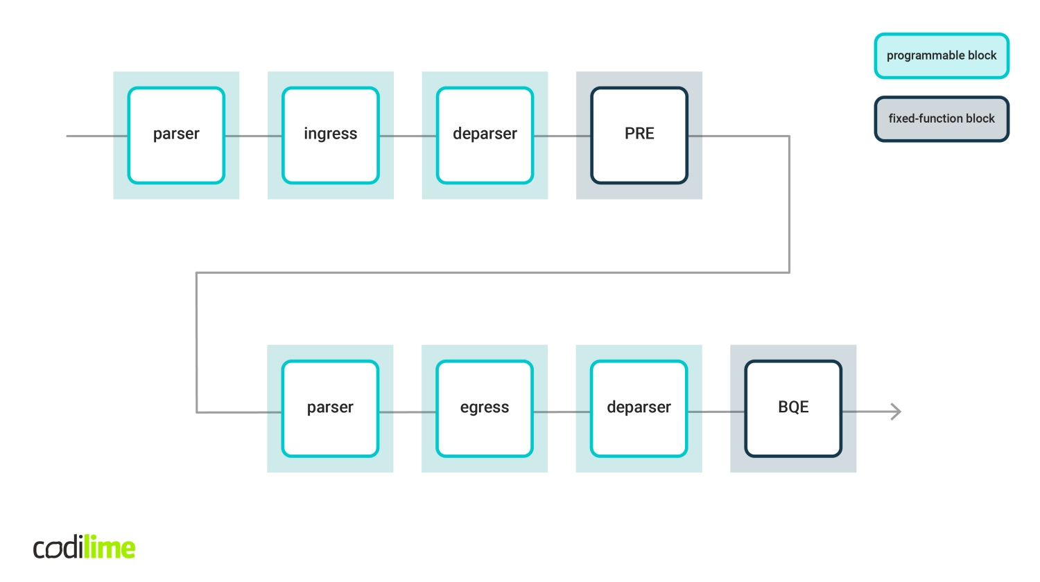
Fig 3. PSA architecture model
The Buffer Queuing Engine (BQE) and the Packet buffer and Replication Engine (PRE) are target dependent blocks. Configurations of those two blocks may vary for different devices. The six remaining blocks are fully programmable using P4. Three of them are designated to provide an implementation of ingress packet processing (with parser, match-action treatment and deparser blocks). The other three blocks represent egress processing based on the same principle.
Another quasi-standard architecture is “v1.0 switch model”, also known as V1Model. V1Model was introduced to propose a kind of interim architecture until the PSA standard is ready and properly defined. V1Model is in fact a P416 switch architecture that models a fixed switch architecture from the P414 specification. In that context, V1Model facilitates the translation of P4 programs originally written in P414 to the P416 version. An example target that supports V1model is a software switch called BMv2, a popular tool for testing P4 programs, e.g. in emulated network environments like mininet.
How to make it work?
Although P4 itself appears to be a relatively simple language next to more popular programming languages, the entire P4 environment may seem complex at first glance. If you want to write a P4 program for a given target, you must first check which architecture model the target supports. Your P4 code must be in line with the architecture, i.e. with the limitations it introduces and capabilities it offers. The target manufacturer provides the compiler, which takes your P4 program code as an input and generates a target-specific configuration binary, which is then loaded into the target. Since that time, tables and other objects defined in your P4 code are present in the dataplane. The only entity that is still missing is the control plane. You can either build it on your own or use software (like an SDN controller) by extending it with a set of functions enabling effective communication with your newly created dataplane. This gives you the whole picture. The dataplane can now be manipulated by the control plane during runtime (see Figure 4).
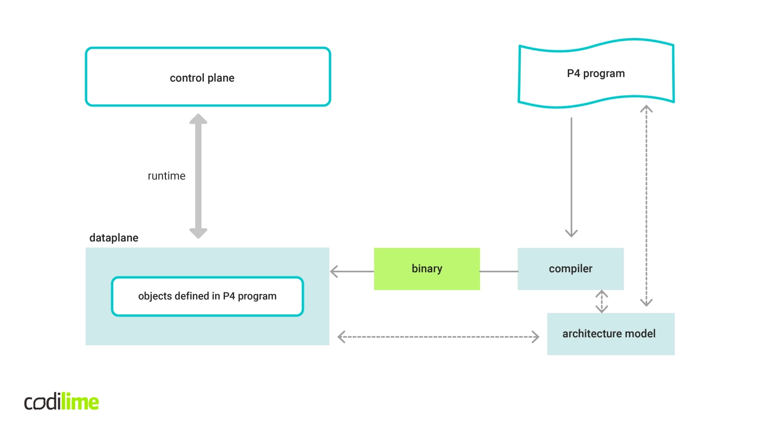
Fig 4. P4 code compilation and execution
The term runtime refers to operations that take place after initial configuration of the target. These include populating tables for further packet processing, updating a forwarding element’s configuration, etc. An example of such a runtime specification is P4Runtime, which provides a standard runtime control API for P4-defined dataplane. This is a gRPC/protobuf-based API, which allows for automatic generation of client/server code for many languages. The P4 Runtime API can be used for both local or remote control plane applications. However, it is worth noting that P4Runtime can work only with P416 or a later version. P414 programs are not supported natively—translation into P416 must be done beforehand.
P4 use cases
So in what areas can P4 really help? There are interesting use cases for both datacenter networks, enterprise networks and telco networks. Some examples have been grouped into categories below:
- Flexible leaf-spine fabric
P4 can help a lot in building flexible multi-purpose leaf-spine fabric. It could be based on white box switches, for instance, and thanks to using a P4-programmable dataplane, the fabric would be easily reconfigured when needed. Such a fabric can serve various workloads related to web-scale, enterprise or telco applications whilst allowing for effective processing of different traffic patterns like flat IP/Ethernet, VLAN-tagged flows (including QinQ), MPLS flows, tunnelled traffic (VXLAN, GRE) etc. at the same time.
>> Do you know the differences between VLAN vs VXLAN?
- VNF-offloading
Deploying VNFs on x86 servers follows general NFV principles and as such can provide a lot of benefits. However, in many scenarios this may be not the optimal way to execute some network functions. Recently, the concept of CUPS (Control and User Plane Separation) has been gaining popularity. CUPS decomposes a given network function into control and user plane parts. An example might be a vBNG or vSPGW. In such a case, protocol-specific headers like PPPoE and GTP, respectively are processed by the P4 fabric switch while the control plane part is still deployed as a virtual appliance on the server. Another interesting example of VNF offloading would be to execute some typical network functions directly on a programmable HW like a switch or smartNIC in the DC environment. An example of such functions would be a firewall, a NAT or a load balancer.
- Service chaining
This use case can be relevant for a wide variety of targets like physical switches, NIC, software switches, etc. The idea is to employ a P4-defined dataplane in the process of creating service chains between virtual or physical service appliances (or mixed). Thanks to the high flexibility P4 offers, sophisticated forwarding rules can be defined and executed for the traffic flows. The matching can be handled using a combination of protocol header fields and user-defined metadata.
- Inband Network Telemetry (INT)
Some people believe this use case is the P4 killer-app. This is because P4 allows you to program dataplane to gather much more information about the network state than what we can determine today using traditional tools, with the simplest of those being the well-known ping and traceroute. The idea of INT is to gather telemetry metadata for each packet such as packet routing paths, ingress and egress timestamps, latency the packet has experienced, queue occupancy in a given node, egress port link utilization etc. Those metrics can be generated by each network node and sent to the monitoring system in the form of a report. Another method is to embed them into packets at every node the packet visits on its routing path and finally remove them in designated nodes that will send them aggregated to the monitoring system.
Summary
The main reason why more and more people are turning to P4 is that it allows you to have a real impact on what your network does and how it does it. This has never been possible to such an extent. Will P4 solve all your problems, then? Probably not, but if properly used it will increase the efficiency of your network resources to better handle service workloads.

